2-DOF Azimuth Thruster
A two-axis underwater thruster: mechanism design, force and torque measurements, and an empirical model built with signal compression.
Method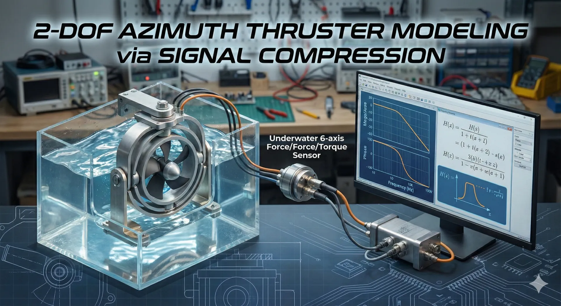
Research question
How does a changing thrust direction change the measured response?
The work connects a two-axis mechanism, force and torque measurements, and an empirical model for control design.
Method
From a physical response to a model.
- Excitation
Drive the mechanism
Apply the test signal while varying the thruster output and axis conditions.
Controlled input - Measurement
Record force and torque
Use a six-axis sensor and account for the difference between sensor and mechanism coordinates.
Response data - Signal processing
Reconstruct the response
Use the Signal Compression Method to estimate a linear impulse response without a physical impact.
Estimated response - Identification
Fit and compare
Fit transfer-function coefficients in MATLAB and compare the model with experimental data by axis.
Empirical model
Design choices
What the design had to account for.
Balance the mechanism before fitting the model
The gimbal uses a counter-mass to address imbalance. Mechanical inertia remains part of the identification problem; it cannot be removed by curve fitting alone.
Use a test signal instead of a physical impulse
Signal compression provides an equivalent-impulse approach to studying the response without striking the hardware.
Put measurements in the same frame of reference
Coordinate and position compensation precede comparison. Otherwise sensor placement can be mistaken for the dynamics of the thruster itself.
Research record
The experiment and its limits.
The research record describes the mechanism, measurement setup and modeling method. It also records why performance differs by axis and identifies lighter gimbal design and nonlinear compensation as further work.
This account summarizes the author's research notes. Raw measurements and independently reproduced results are not included on this page.
Reference material
- Research
- Empirical thruster modeling
- Method
- Signal Compression Method
- Record date
- 2020.08
The external bibliographic reference listed in the research record.
Read the technical notes
Mechanism and instrumentation
Two servo motors control yaw and pitch. The documented setup uses NI CompactRIO and a six-axis force/torque sensor. Rotary seals, O-rings and cable glands address the underwater mechanical interfaces.
Signal and coordinate processing
The record describes FFT-based phase processing and inverse transformation, followed by coordinate and sensor-position compensation. The goal is to separate a useful linear response from nonlinear effects.
Model identification
MATLAB fmincon is used to fit transfer-function coefficients to experimental data. The comparison is made by force and moment component, rather than treating every axis as equally well represented.
Tools and methods
- NI Compact RIO
- LabVIEW
- MATLAB
- Signal Compression Method
- System Identification