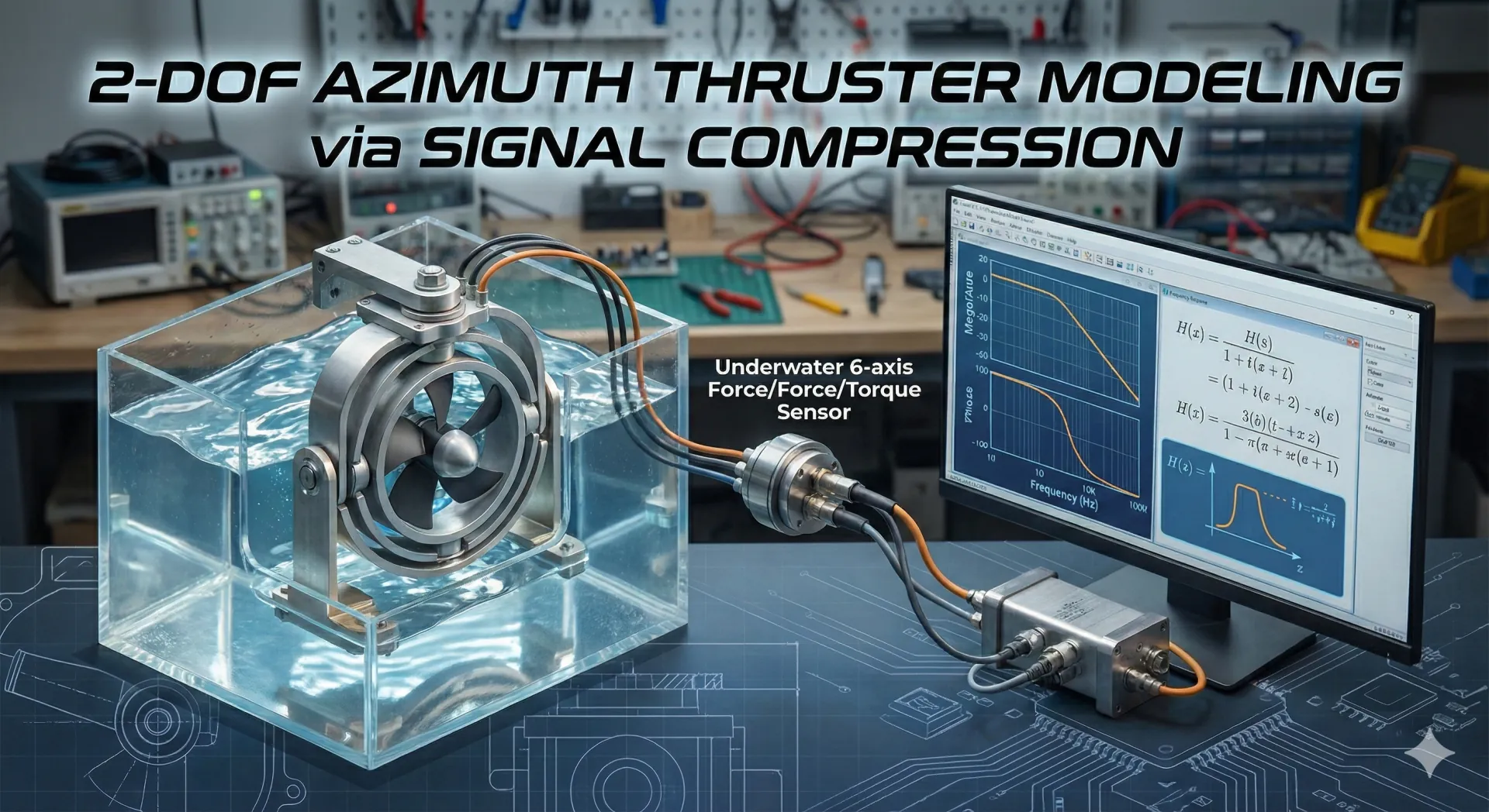
2-DOF Azimuth Thruster

Physical · 물리 / Marine Robotics

2-DOF Azimuth Thruster

복잡한 유체역학 환경에서 2자유도 애지머스 추진기의 전달함수를 추정하기 위해 실험 기반 수학 모델을 구축한 연구 프로젝트입니다.

역할
1인 개발 · 아키텍처, 구현, 운영 도구
기간
2020.08
맥락
Academic
01 / 핵심 요약

복잡한 유체역학 환경에서 2자유도 애지머스 추진기의 전달함수를 추정하기 위해 실험 기반 수학 모델을 구축한 연구 프로젝트입니다.

DECISION / A시스템 과제

무엇이 시스템을 어렵게 만들었는가.

주파수 응답 실험만으로는 고주파 데이터 확보가 어려웠고, 짐벌 구조로 인한 비선형 진동/오버슈트가 존재했습니다.

DECISION / B엔지니어링 해법

어떤 경계와 흐름으로 답했는가.

신호압축법(SCM)과 동특성 보정을 결합해 선형/비선형 성분을 분리하고, 최적화 기반 곡선 피팅으로 모델을 추정했습니다.

03 / 기술 필드
01NI Compact RIO02LabVIEW03MATLAB04Signal Compression Method05System Identification
04 / 상세 기록

1. Background & Problem Definition

  • Project Name: Empirical Modeling of 2-DOF Azimuth Thruster based on Signal Compression Method
  • Research Necessity:
    • Existing underwater robots use multiple fixed thrusters, resulting in large volume and weight. To solve this, a 2-DOF Gimbal Mechanism capable of changing direction with a single thruster is needed.
    • Underwater propulsion systems have complex hydrodynamic characteristics, making Analytical Modeling extremely difficult.
    • Traditional frequency response experiments struggle to obtain high-frequency data, limiting the establishment of precise control models.
  • Core Objective: Derive an Empirical Mathematical Model covering the entire frequency range (low to high) through actual hardware experiments.

2. Deep Dive into Technologies

A. Mechatronics Hardware Engineering

  • 2-DOF Gimbal Mechanism Design:
    • Designed a structure that freely controls the thrust direction using two servo motors (Yaw, Pitch).
    • Manufactured and mounted a Counter Mass with the same shape and mass (1.35kg) as the servo motor to resolve center of gravity imbalance.
  • Underwater Waterproofing Solution:
    • Applied O-rings to all fastening parts and used Rotary Seals on rotating shafts to block fluid ingress.
    • Applied Cable Glands to prevent water intrusion into motor wires.
  • Electronic Component Configuration:
    • Thruster: Maxon MI60 (Max Thrust 7kgf, Rated 24V).
    • Controller: NI Compact RIO 9049 (Real-time Controller).
    • Sensor: 6-axis F/T sensor (ROBOTUS RFT80-6A01) placed at the top to measure reaction force and moment.

B. System Identification & Signal Processing

  • Signal Compression Method (SCM) Application:
    • Principle: Based on the theory that applying an impulse signal to a system reveals the entire frequency response, but uses an Equivalent Impulse Signal instead of an actual impulse to avoid damaging the physical system.
    • Algorithm Implementation:
      1. Generate time-domain test signal (Frequency band and time delay parameters set to a=450, b=2100).
      2. Convert to frequency domain via FFT (Fast Fourier Transform) and apply phase delay filter.
      3. Compress and restore the system output to time-domain impulse response via IFFT (Inverse Fourier Transform).
    • Advantage: Separates linear and non-linear components in a system containing non-linearities, allowing effective estimation of only linear system parameters.

C. Data Analysis & Modeling

  • Experimental Data Processing:
    • Performed a total of 180 experiments varying thruster output (PWM 55%~95%) and rotation axes (1-axis, 2-axis).
    • Performed coordinate transformation and position compensation using Homogeneous Transformation Matrix since Sensor Frame and Moving Frame positions differ.
  • Transfer Function Derivation:
    • Analyzed the slope of the measured Bode Plot to determine the system Order.
    • Calculated coefficients (k, a, b, c, d, e, g) minimizing error between experimental data (Raw Data) and model using MATLAB's fmincon optimization technique via Curve Fitting.

3. Results & Achievements

  • Model Accuracy Verification:
    • Cross-correlation Coefficient analysis between derived transfer function model and actual experimental data:
      • Mz,1 (Z-axis Moment): 0.83 (Very High Accuracy).
      • Fy,1 (Y-axis Force): 0.75.
      • Fx,1 (X-axis Force): 0.60.
  • Error Analysis & Engineering Insight:
    • Gimbal Inertia: The low correlation coefficient for Fx,1 is due to the large inertia of the gimbal structure causing non-linear overshoot and vibration during rotation.
    • Gravity & Buoyancy Disturbance: Identified that model tracking performance for Fz dropped slightly due to the combined effects of gravity and buoyancy.
  • Conclusion: Confirmed that the proposed 2-axis propulsion system contributes to the Compact Design of underwater robots, and suggested that lightweight gimbal design is essential for future control performance improvement.

4. References & Links

  • Research Paper (PDF): [Download/View PDF](/assets/신호압축법을 이용한 2자유도 애지머스 추진기의 실증적 모델.pdf)
  • RISS Research Information: View on RISS
05 / 실제 증거
2-DOF Azimuth Thruster project evidence
ACTUAL PROJECT ASSET / NOT GENERATED